
The Impact of Differential Trace Symmetry
Today,let's talk about the symmetry of differential signal channels.
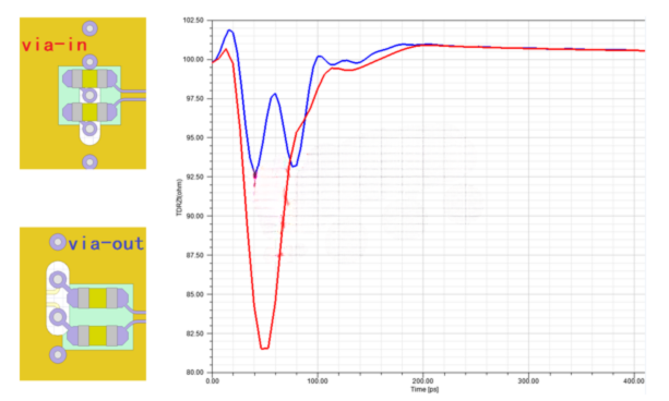
This was sparked by a recent article on AC coupling capacitors, titled "Have You Ever Considered This to Save Space on AC Coupling Capacitor Vias?" At that time, the analysis was from the perspective of impedance continuity. It showed that for a 100-ohm differential signal, the "via-in" style had significantly lower impedance than the "via-out" style, resulting in a larger impedance fluctuation.
Then, a sharp-eyed reader asked: "If the differential impedance is controlled to 85 ohms, wouldn't the 'via-in' style offer better impedance continuity?"
That's an excellent question, but answering it isn't straightforward. We need to look at it from a different angle.
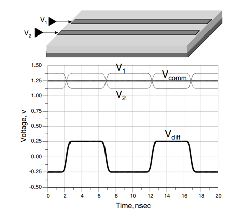
Before we dive in, we first need to understand the composition of a differential signal. A signal transmitted through a differential channel can be broken down into a differential mode component and a common mode component. The differential mode component carries the useful information, while the common mode component does not.
In an ideal scenario, the common mode signal is constant and has no adverse effects. In reality, however, any asymmetry in the differential channel will cause changes in the common mode signal. You can think of it this way: the channel's asymmetry causes some of the energy that should be in the differential signal to be converted into a common mode signal.
As for the harm caused by a changing common mode component, if you know its other name—common-mode noise—you'll likely sit up and take notice. And common-mode noise carries the risk of electromagnetic interference (EMI).
In short, asymmetry in a differential channel converts part of the useful signal energy into noise.
To quantitatively analyze this mode conversion in differential signals, we must bring out the S-parameters.
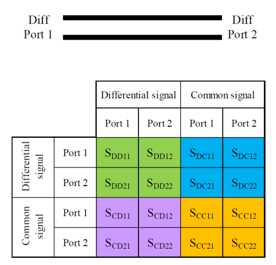
Among them, SCD represents a differential signal input and a common mode signal output. It is used to measure the conversion from the differential mode component to the common mode component.
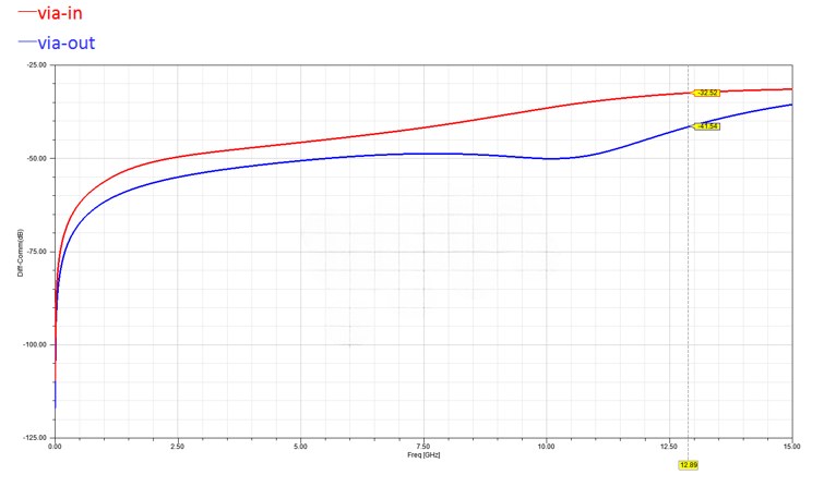
Let's apply this specifically to the two via styles for the AC coupling capacitors. When the differential trace characteristic impedance is 100 ohms, the comparison of the mode conversion parameter, SCD21, for the two cases is as follows: The SCD21 for "via-in" is consistently higher than for "via-out," indicating that within the frequency band of interest, the "via-in" style converts more differential signal energy into common-mode noise.

Next, here is the SCD21 comparison for the 85-ohm impedance case that everyone was curious about:
Clearly, even when the differential trace impedance is controlled to 85 ohms, the SCD21 for "via-in" is still consistently about 10 dB higher than for "via-out," similar to the 100-ohm case.
Returning to the beginning of the article, why do we say the symmetry of a differential channel is so important? To prevent sharp-eyed readers from asking further questions, we will make one more comparison, which should make everything clear.
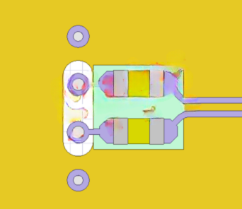
The symmetry of the "via-out" style is better than "via-in," but there is still room for improvement. At the very least, the via fan-out can avoid 45-degree angle exits. By aligning them with the signal flow direction, the P and N traces of the differential pair can achieve perfect symmetry (hereafter referred to as "symmetrical via"):
Here is the SCD21 parameter comparison for the three cases with 85-ohm differential impedance:
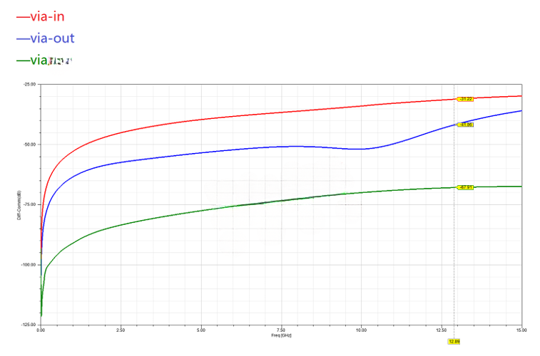
As expected, the "symmetrical via" design, which has the best symmetry, also has the lowest SCD21.